System Context Mapping
Understand and model the scope and environment a solution will operate in, i.e. systems and actors the solution will be interfacing with.
Wolfram Richter
What Is System Context Mapping?
System Context is a way to capture, describe and communicate our understanding of a systems boundary and environment it is operating in. It consists of a simple to understand diagram and optionally a table with additional information.
Tools to use:
- Pen & Paper (large) or
- digital drawing & sharing tools
Diagramming:
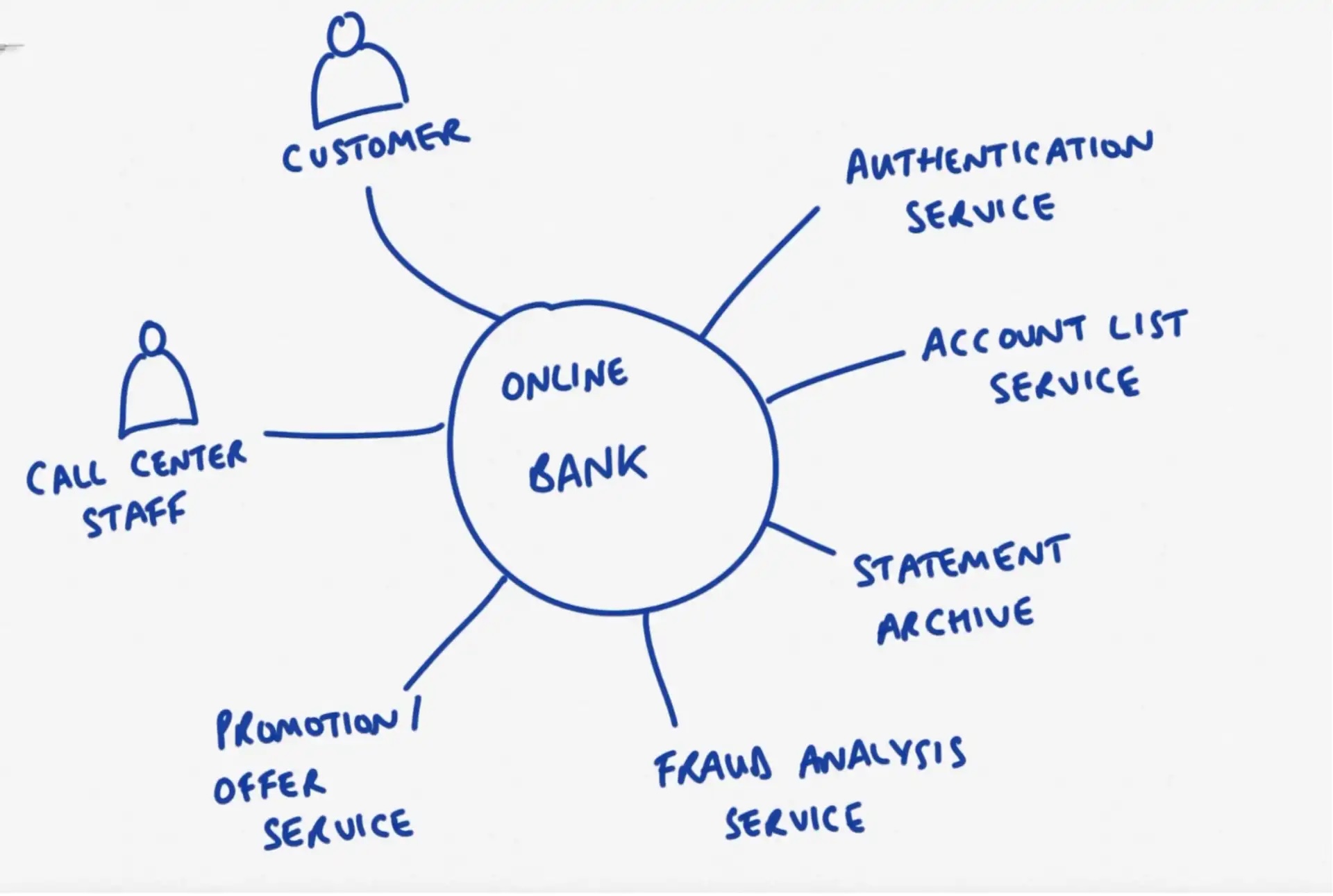
- The system under consideration is depicted as a {square|circle|square with rounded corners} in the middle of the drawing area.
- External systems and human actors (roles) are placed around the system under consideration. They may be given a unique ID to correlate them to information in the database (see below)
- Connectors (lines) are drawn between the system under consideration the the external systems/actors.
- Additional information, such as data flows (data items + direction) may be attached to the connectors
Table / Database:
Depending on the projects complexity, you might want to capture additional details about actors and external systems in a table, such as:
- Unique ID (to be able to uniquely identify a system across different diagrams)
- Description of the System or Actor Role
- Systems:
-
- System Owner Contact Information
- Link to interface / API description
- Link to CMDB record
- Lifecycle information (is the system to be decommissioned within the project’s lifecycle?)
- Actors:
-
- LDAP query to identify in corporate directory
Hints & Caveats:
- In this diagram, the system under consideration is treated as a black box. The focus is reasoning about the system’s context. Other diagram types are used to depicts the system’s inner workings. Avoid adding details about the system’s internals to the diagram.
- Do not try to depict end-to-end process flows or connections between external systems. This would clutter the diagram and lessen your ability to reason about the system under consideration.
- System Context Mapping should not be confused with the “System Diagram” (a.k.a. Architectural Overview) practice that depicts a high level understanding of a system’s inner workings.
Why Do System Context Mapping?
Modeling the system context helps to understand a system's boundaries, i.e. what is in scope and what is out of scope of the system. It allows you to reason about interfaces to surrounding systems and actors using the system, to reason about data flows and to compile a database of related information.
The system context informs and should be in sync with many other diagrams that depict interactions with the world outside of it, such as use case diagrams, component models, operational models, etc.
How to do System Context Mapping?
System context modeling can be executed alone or in teams. A majority of its value comes from using the generated artifacts to communicate and align your understanding with others.
You can and should revisit and adjust your system context model throughout the project as you learn more about the system under consideration.
There is (to our knowledge) not a single best approach on how to create a system context diagram / facilitate a system context modelling session.
As an exercise to get familiar with the technology, the following has worked for us:
- After listening to/participating in a discovery conversation with project stakeholders, the participants visualize their understanding of the system context in the form of a diagram.
- Once completed, participants exchange their drawings with other participants to discuss commonalities and differences in understanding.
- Once the diagram stabilizes and a common understanding is achieved, additional information can be captured e.g. in terms of information flows or in tabular fashion.
Look at System Context Mapping
Links we love
Check out these great links which can help you dive a little deeper into running the System Context Mapping practice with your team, customers or stakeholders.
